Yet Another Pocket Color (YAPoCo) by NatalieTheNerd
Yet Another Pocket Color by NatalieTheNerd
I decided to go with NatalieTheNerd’s YAPoCo for my first Pocket Color. I began with getting a pre-built LoCo board to get an idea of a completed board for comparison. I also wanted to build something that I could easily order PCBs and build without having to order new components.
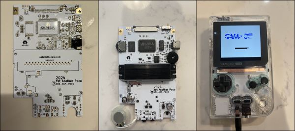
NTN is self-taught and incredibly talented and shares her work on GitHub. Her YAPoCo PCBs can be ordered using GERBER files from any PCB house. The YAPoCo is built with a donor GBC and minimal additional parts.
This was my very first time ordering a PCB and I used JLCPCB. The first round of boards I ordered was actually lost during shipping from Hong Kong and I had to re-order another set. Unfortunately, the timing was not great and I had to pay quite a bit to receive them due to issues with delays leading to my second package getting caught up right in time for the changes in customs and taxes in May 2025.
In preparing to build the YAPoCo, I used several resources that I found were helpful:
-
Cool Uncle Mods: Gameboy Pocket Color - Tips, Tricks, and More YT video by @yourcoolunclemarisa that goes over her process in building BucketMouse’s MGBC which is a similar process. She goes over helpful tips and tricks such as organization, display options, putting it all together, etc.
-
BucketMouse’s GitHub Documentation - Just read it. Just read it all. At least to know what to you are getting yourself into and how much you may be spending. His documentation is extensive and very very helpful for building these kinds of mods. Again, even though YAPoCo is not his mod this was a helpful read. Additionally his PCB section has a “CPU Pin Functions” photo that is very helpful for guidance when doing re-flows.
-
NatalieTheNerd’s Interactive BOMs!!!!! - I cannot stress how amazingly helpful these were. She has BOMs for GBC and YAPoCo (and the LoCo). These were so helpful especially since the labels on the boards are not always next to the components. Additionally, you can use them to find extra components if you need a replacement for a lost component or a shorted SMD.
To begin the build, I desoldered the larger peripheral components by hand using both electric solder sucker and hot air. To remove the cartridge reader, I used olDirdey’s hollow needle technique. For the remaining SMD parts, I used a hot plate to remove them and organized them into a little cube tray.

To prepare the new board, I used a PCB stencil with solder paste and flux and placed the components. I used a hot plate to pre-fix the smaller components and hot air to finish. I then soldered on CPU, RAM, and FCC, followed by the other external peripherals.
I ended up with having to re-flow the CPU quite a few times in order to get a working GAME BOY screen and eventually to even getting the cartridge reader to read properly and eventually to getting it to read BOTH GB and GBC games. It seemed like an excessive stepwise process that exposed my lack of skill. Again, using BucketMouse’s PCB page was helpful to realize my issues with getting sufficient solder on my CPU pins.
Some small changes I did were just new capacitors and for the LED, I used NTN’s guide on how to change LEDs. I had a bunch of extra resistors from an old board to swap out R7. I used a 40k resistor to reduce the brightness of the LED.
The Build Materials
-
YAPoCo PCB
-
Capacitors (
C32, C35, C38) -
Thumb Wheel to toggle screen settings
-
Power Regulator for IPS Screens (C32 not necessary with updated 5V Regulator)
-
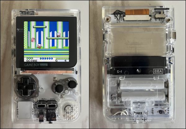
AAA Battery Terminals
-
GBC Donor Board (Fully functioning)
-
Q5 IPS Screen Kit
-
GBP Shell (Q5 ready is ideal)