GBC General Troubleshooting
A symptom-by-symptom checklist for a Game Boy Color that powers on but misbehaves. If your console is completely dead, start with the GBC Power Troubleshooting guide instead — this page assumes you have working power rails.
This guide is adapted from BucketMouse’s troubleshooting notes (written for their replacement-board project, generalized here for stock CGB boards too), the community common-issues documentation at gbwiki.org, and the CPU pinout documented by Natalie the Nerd. Component designators follow the official CGB schematic.
A note on designators: if you’re building a reproduction board rather than repairing a stock unit, your board’s silkscreen may use its own numbering — check its BOM. The functional checks below apply either way.
Before anything else
The boring causes are still the most common ones. Before chasing signals:
- Isolate console vs. game. Try another game — if several games misbehave the same way, it’s the console. Try the game in another Game Boy — if it fails there too, it’s the cart.
- Inspect for cold or cracked solder joints, especially anywhere the board flexes (cart slot, jacks, switch).
- Clean the cartridge slot and cartridge contacts with IPA (90 %+).
- Clean the power switch — a dirty switch causes more “weird” faults than any chip. Spraying contact cleaner or IPA into it and working it back and forth helps, but treat that as a temporary fix; the durable repair is opening the switch and cleaning the contacts inside (the CGB switch body has a small latch — go gently). Do this even if it isn’t your problem; it improves the switch action regardless.
- Reseat every ribbon/FFC cable fully and close its bale.
Power LED flickers, low-battery light comes on early, or the console randomly resets
Almost always the power switch again — oxidation inside the switch adds resistance, and the rail sags under load. Clean it properly (see above). If a thorough internal cleaning doesn’t cure it, move on to aging capacitors and the battery terminals, per the power guide.
Severe glitches at start-up, or plugging in headphones resets the system
Classic symptoms of a marginal supply or a miswired audio path:
- On rebuilt boards: verify the orientation of the tantalum capacitors around the power and audio circuits — the stripe on a tantalum marks the POSITIVE side, the opposite convention of an electrolytic. A reversed tantalum drags the rail and can behave exactly like a power fault.
- On rebuilt boards: confirm the resistor values around the headphone jack against the BOM — wrong values here can pull the rail down when a plug is inserted.
- Clean the power switch properly (see above). A high-resistance switch drops voltage under the current spike of startup or headphone insertion.
- Check the headphone jack’s switch contact (see the audio section below) — a jack that thinks headphones are half-inserted can upset the audio amp’s load.
No sound, or bad-quality sound
First split the problem in half: plug in headphones.
Headphones work, speaker doesn’t:
- Check continuity from the headphone jack’s switch contact (pin 5 on the jack, top-right corner viewed from below) to ground. With nothing plugged in, this pin should read connected to GND — that’s the physical switch that routes audio to the speaker; corrosion holds it open and the speaker never comes back on. If it doesn’t beep, clean the jack (P5) thoroughly with contact cleaner, or replace it (a custom part — donor consoles are the realistic source).
- Test the speaker itself: desolder it and measure resistance across the terminals — a good speaker reads about 8 Ω; anything else (or open) means replace it (SP1). Speakers that die are often a sign the electrolytic capacitors are due for replacement too.
Both speaker and headphones are bad or silent:
- Clean the volume wheel (VR1): it can’t be disassembled, so drip contact cleaner or IPA into it and spin it back and forth through its full travel several times. Scratchy, cut-out-y volume is almost always this. Fully corroded → replace it.
- Fuzz or static that changes when you twist the headphone plug is the jack itself — clean it out with contact cleaner on a swab or pipe cleaner.
- Reflow the audio amplifier (U3) and its surrounding capacitors.
- Reflow the CPU’s sound output pins — pins 37 (SO1 / right) and 38 (SO2 / left) on the CGB CPU — and trace continuity from them toward the volume pot and amp.
White screen, glitchy display, wrong colors, or stuck on the boot logo
- Make sure the screen ribbon is inserted all the way into the LCD connector (P2) and the bale is pushed fully down — the number-one cause after a screen swap.
- Reflow the work-RAM chip (U2, the SRAM next to the CPU) and check every pin is bonded — a floating SRAM pin produces glitchy or frozen screens.
- Reflow the FFC connector (P2) itself.
- Reflow the CPU (U1) pins, particularly the screen-signal groups (pin numbers below).
- Wrong colors on an IPS-modded unit: check you haven’t cycled the kit’s palette — most IPS kits have a touch sensor that steps through color modes.
- Stuck on the boot logo only with a game inserted: see the cartridge section below — a bad contact on a data line garbles the logo check.
Cartridge won’t read: garbled boot logo, freezes, corrupt sprites
The GBC compares the Nintendo logo stored in the cart against its internal copy at boot — if it can’t read the cart cleanly, you get a garbled logo and a freeze. Random freezes and corrupt or black-square sprites (famous in Pokémon games) are the same class of fault: a marginal connection on the cart’s data lines or its SRAM.
First isolate console vs. cart (try another game / another console), then:
- Clean the cart contacts: IPA on a cotton swab, repeat with fresh swabs until one comes away clean. With the cart open, an artist eraser rubbed along the pins works even better.
- Clean the console’s cart slot: a credit-card-sized object wrapped in lint-free cloth with IPA, moved straight in and out (never side to side).
- Cracked solder joints inside the cart: these thin PCBs flex with every insertion, and hairline fractures form at the ROM (lower right) and MBC (top left) chip pins. Gently prod each pin — a good joint doesn’t move. Reflow with flux. Corrupt-sprite issues specifically point at the cart’s SRAM (lower left) and MBC joints.
- Never do these: don’t blow into carts or the console (spit corrodes), don’t sand the contacts (sandpaper ruins the plating permanently), and don’t solder onto the gold edge contacts — solder oxidizes and will smear into your console’s cart reader.
Function missing? CPU pins to check
When one specific function is dead and everything else works, go straight to the CPU pins that carry it — inspect, reflow, and trace continuity to the next component. Pin numbers are for the CGB CPU (all revisions except CGB E), per Natalie the Nerd’s pinout.
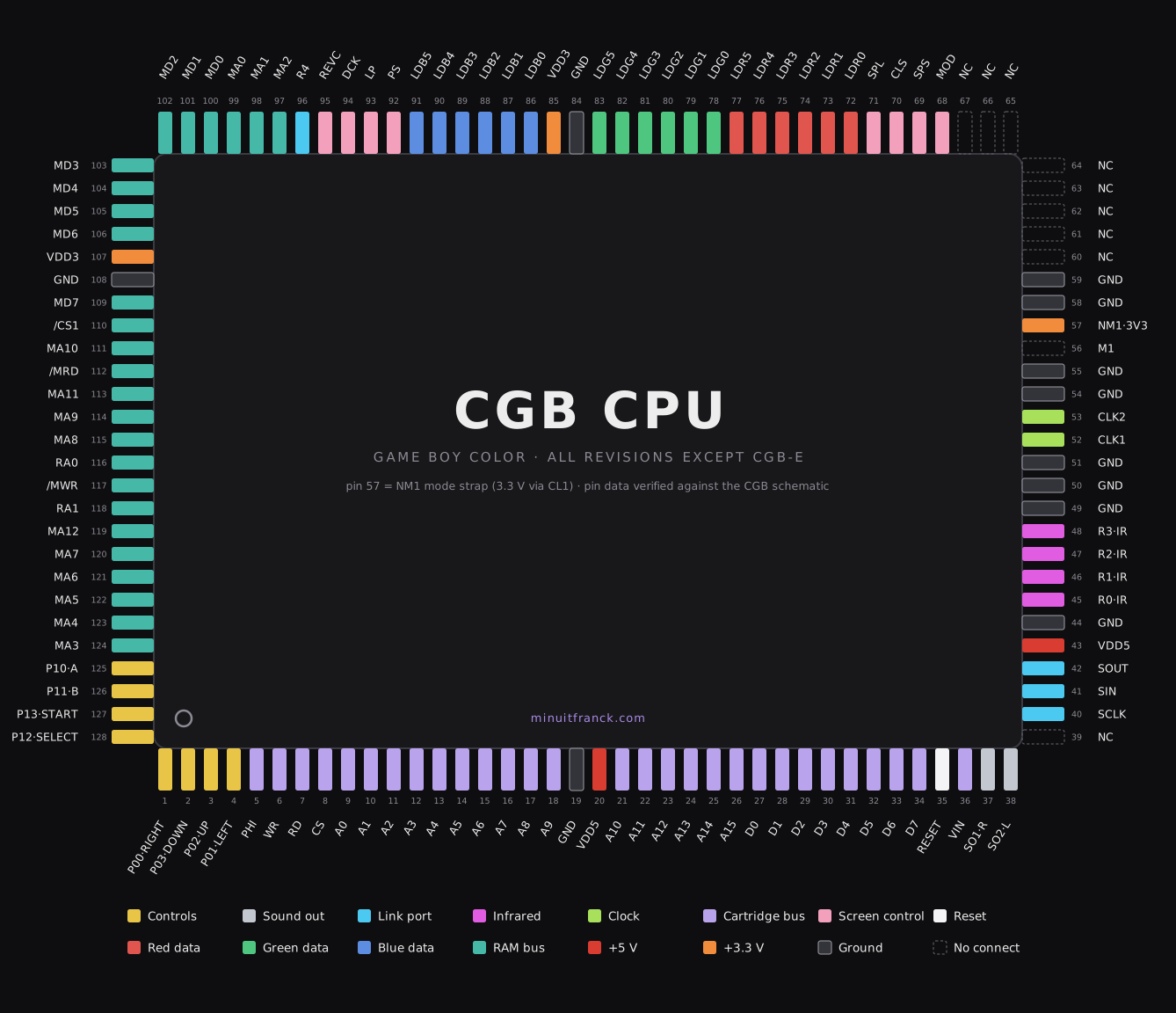
Our own pinout reference, drawn for this site — click to open full-size. Pin assignments independently verified against the CGB schematic (including pin 57, the NM1 mode strap, often mislabeled as a plain 3.3 V supply pin).
| Missing function | CPU pins | Also check |
|---|---|---|
| D-pad (all or some directions) | 1–4 (P00–P03) | PCB button contacts, conductive pads |
| A / B / Start / Select | 125 (A), 126 (B), 127 (Start), 128 (Select) | PCB button contacts |
| Sound (speaker and headphones) | 37 (SO1/right), 38 (SO2/left) | Volume pot VR1, amp U3 |
| Link cable | 40 (SCLK), 41 (SIN), 42 (SOUT) | Link port pins, series resistors |
| Infrared | 45–48 (R0–R3 / IR) | IR window components |
| Won’t boot at all (power OK) | 52/53 (CLK1/CLK2), 35 (RESET) | Crystal X1 (8.388608 MHz), reset IC |
| Cartridge not read / logo garbage | 5 (PHI), 6 (WR), 7 (RD), 8 (CS), 9–18 + 21–26 (A0–A15), 27–34 (D0–D7) | Cart slot pins, cart edge |
| Screen signals | 68–71 (MOD/SPS/CLS/SPL), 72–77 (red), 78–83 (green), 86–91 (blue), 92–95 (PS/LP/DCK/REVC) | Ribbon seating at P2 |
| Power to CPU | 5 V: pins 20, 43 · 3.3 V: pins 85, 107 | See the power guide |
A magnet-arm magnifier or a loupe makes CPU pin inspection far easier — look for pins that sit proud of their pad, hairline cracks at the solder fillet, and flux residue hiding a non-joint.
Sources & credits: troubleshooting checks adapted from BucketMouse’s build notes and the community documentation at gbwiki.org; CPU pinout and schematic reference by Natalie the Nerd. This guide was researched and written with the help of Claude (Anthropic’s AI) — I’m a newbie working alone, piecing things together from trial and error, community Discords, Google, and YouTube, with AI helping me aggregate it all. Corrections welcome — email me.